Pipe
Flanges
UAE stockist and global supplier of weld neck, blind, slip-on, socket weld, threaded, lap joint, long weld neck, orifice, spectacle blind, nipo, and expander flanges — in carbon steel, stainless, alloy, duplex, and super duplex. ASME B16.5, ASME B16.47, API 6A, DIN/EN standards. All pressure classes. All facing types.
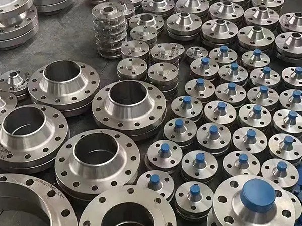
ASME B16.5 / B16.47 / API 6A Flanges
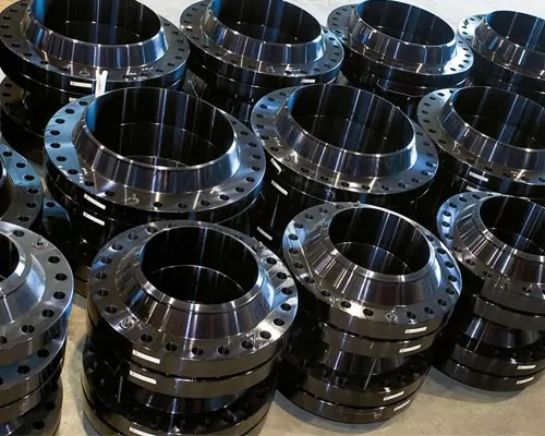
Naftaar International FZE is a UAE-based stockist and global supplier of a comprehensive range of pipe flanges for the oil & gas, petrochemical, power generation, water treatment, construction, and offshore sectors. Our flange range covers all types — weld neck (WN), slip-on (SO), blind (BL), socket weld (SW), threaded (THD), lap joint (LJ), long weld neck (LWN), orifice (OR), spectacle blind, spade & ring spacer, nipo flange, reducing flange, and expander flange — in every pressure class from Class 150 to Class 2500, and API 6A 2000 to 20,000 psi WP.
All flanges are available in carbon steel (ASTM A105N), low-temperature carbon steel (ASTM A350 LF2), alloy steel (ASTM A182 F11/F22/F91), stainless steel (ASTM A182 F304/316/321/347), duplex (A182 F51), and super duplex (A182 F53) — supplied with original EN 10204 Type 3.1 mill test certificates from our UAQ Free Trade Zone facility with fast worldwide delivery.
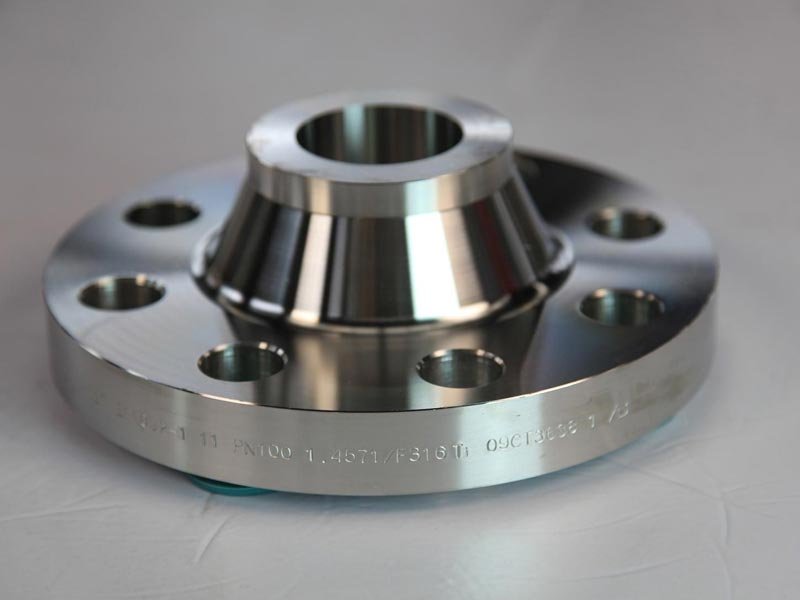 Most Common
Long tapered hub bore-welded to the pipe. Highest integrity flange — ideal for high-pressure, high-temperature, and cyclic service. Hub transfers stress to the pipe wall.
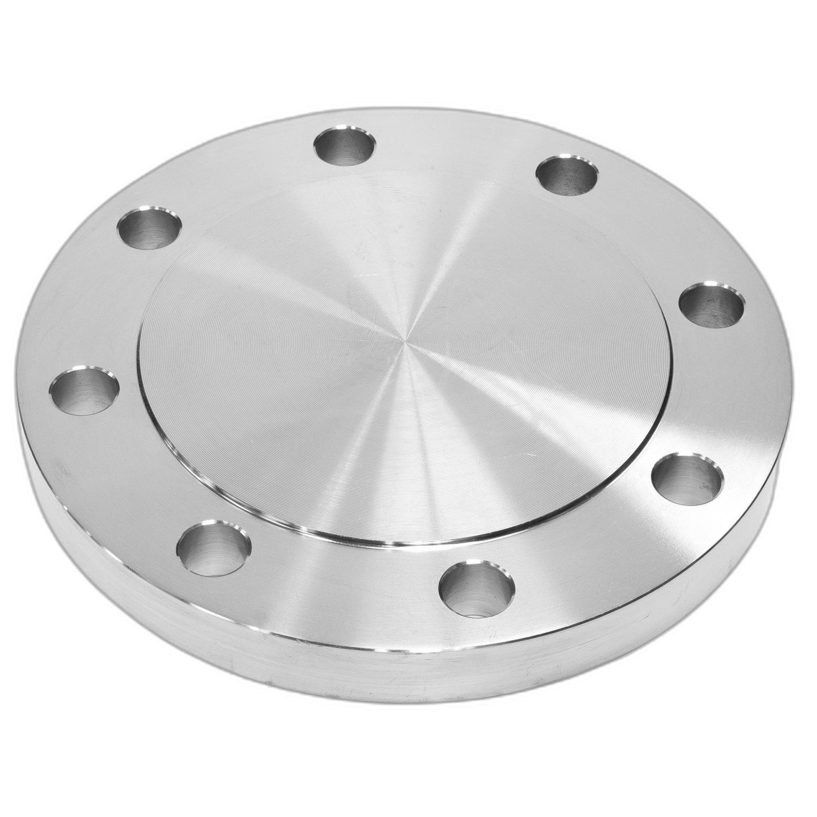 Isolation
Solid disc used to blank off ends of pipework, vessels, or valves. Subject to bending stress from pressure — must be thicker than other flange types. Commonly used as test blanks.
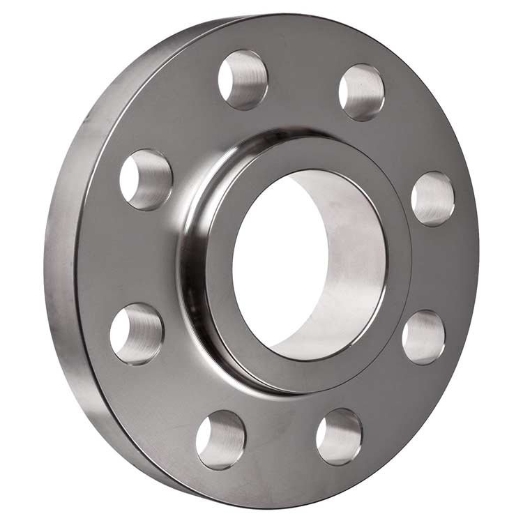 General Service
Slides over pipe end, fillet welded inside and outside. Lower pressure resistance than WN. Cost-effective for standard service. Not recommended for high-cycle, corrosive, or critical service.
Line Isolation
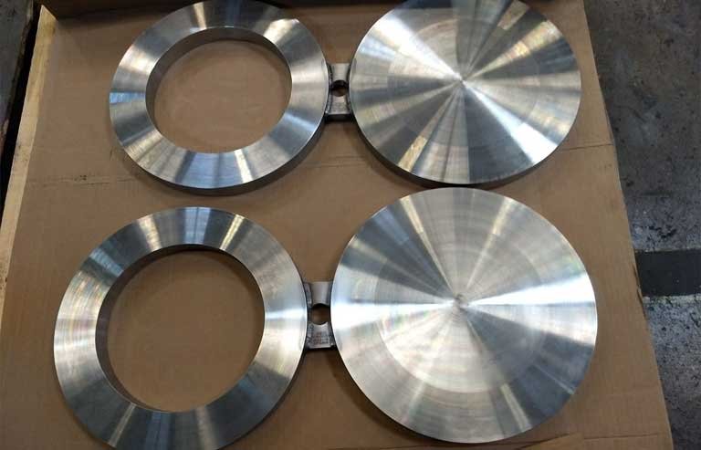
Spectacle blind: combined blind disc and ring spacer in one figure-8 fabricated piece. Spade is blind only; ring spacer is open ring. Used for positive isolation of pipelines during maintenance.
Large Diameter
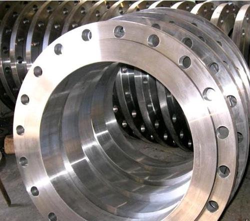
Flanges for NPS 26" to 60" in pipeline and process applications. Series A (MSS SP-44) and Series B (API 605). Used on large-bore transmission pipeline isolation and launcher/receiver connections.
API / Wellhead
High-pressure flanges for wellhead, Christmas tree, and BOP connections in upstream oil & gas. Working pressures from 2,000 to 20,000 psi. Ring gasket seal (R, RX, BX types).
Flange Facing Types — RF, FF, RTJ, T&G, M/F
The sealing face of a flange is critical to joint integrity. The correct facing type must match the gasket type being used, and must be consistent throughout the flanged joint. Mixing facing types (e.g. RTJ with raised face) is not acceptable. Naftaar supplies flanges in all standard facing configurations per ASME B16.5.
Most common facing type. A raised ring surface (1.6mm height for Class 150/300; 6.4mm for Class 400+) concentrates the bolt load over a smaller gasket area for improved sealing. Used with spiral wound, soft-cut, or sheet gaskets.
Face is flush with the flange face — no raised ring. Used with full-face gaskets when connecting to cast iron, ductile iron, or non-metallic flanges where the mating flange would crack under bolt bending stress from RF.
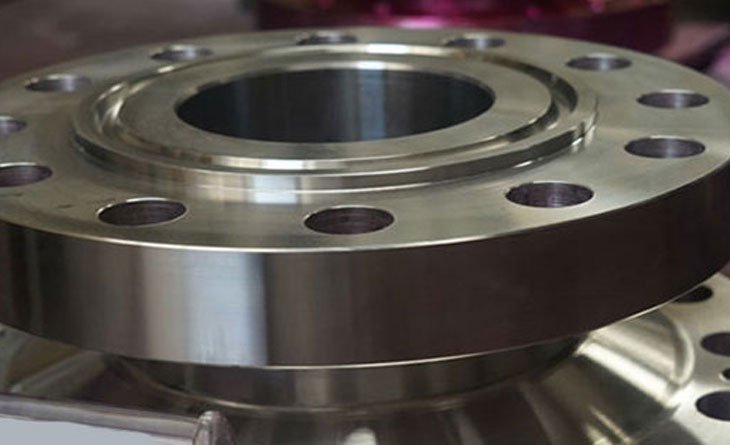
Precision-machined groove machined into the flange face accepts a metallic ring gasket (oval or octagonal profile). Highest-integrity sealing face for high-pressure, high-temperature, and critical applications. Cannot be reused after break-out.
One flange has a raised male contact face; the mating flange has a corresponding female recessed face. The gasket is contained and centred within the female face. Provides superior gasket retention vs RF.
Similar to male/female but with a narrower tongue and groove profile. The gasket is retained and compressed within the groove. Provides excellent gasket alignment and prevents blow-out. Used in heat exchangers and critical joints.
Similar to large male/female but with smaller contact area dimensions per ASME B16.5. The gasket is contained within the smaller profile, providing better gasket alignment in restricted-space applications.
🔴 UAE Stock — ASME B16.5 A105N Flanges · Class 150, 300 & 600 from Warehouse
Naftaar maintains ready stock of ASTM A105N carbon steel flanges in weld neck (WN), slip-on (SO), and blind (BL) types in Class 150, 300, and 600, sizes ½″ to 24″ NPS, raised face (RF) as standard — all held with original EN 10204 3.1 mill test certificates at our UAQ Free Trade Zone warehouse. RTJ face and other materials/classes available on order. Contact sales@naftaar.com for same-day quotation.
Every Flange Type — Explained
Weld Neck Flange (WN)
The weld neck flange is the most widely used and most reliable flange type for high-integrity piping. It has a long tapered hub that is bore-welded (butt-weld) to the pipe end, forming a seamless transition between the pipe and flange bore. The tapered hub gradually transfers stress from the flange to the pipe wall, eliminating the stress concentration at the flange-to-pipe junction. Weld neck flanges are the only flange type that can accommodate full radiographic examination of the weld joint. They are specified for high-pressure, high-temperature, cyclic loading, cryogenic service, and any application where reliability is paramount.
Bore specification: The bore of a weld neck flange must match the internal diameter of the connecting pipe — specified by nominal pipe size AND schedule (e.g. 6" NPS, Sch 80). This is critical — always specify the pipe schedule when ordering WN flanges to ensure correct bore alignment and wall transition.
Blind Flange (BL)
A blind flange is a solid disc with no bore, used to blank off the end of a nozzle, pipeline, or valve. Despite having no bore, the blind flange is one of the most highly stressed flange types — it experiences bending stress across its full diameter from the bolt load and internal pressure. For this reason, ASME B16.5 blind flanges are made significantly thicker than other flange types of the same class. Blind flanges are commonly used as test blanks during hydrostatic testing, as permanent end closures, and as access blanks on vessels and headers.
Slip-On Flange (SO)
The slip-on flange slides over the pipe OD and is welded in place with two fillet welds — one on the inside bore (recessed) and one on the pipe end face. The two fillet welds provide the connection strength and joint integrity. Slip-on flanges are simpler and cheaper to fabricate than weld neck flanges, but they are less suitable for high-cycle, high-pressure, or corrosive service due to the fillet weld quality limitations and the crevice between the pipe OD and flange bore. Not permitted by some specifications for NACE sour service or cyclic/fatigue service. Bore size = pipe OD + clearance (not schedule-specific like WN flanges).
Socket Weld & Threaded Flanges (SW / THD)
Socket Weld Flange: Used for small-bore (½" to 2" NPS) high-pressure piping. The pipe is inserted into the socket bore (with a small gap of ~1.5mm maintained between the pipe end and socket bottom to allow weld shrinkage) and a single fillet weld is applied externally. Provides a strong joint suitable for high-pressure service. A gap between pipe end and socket bottom is critical to prevent weld cracking from thermal expansion.
Threaded Flange: Similar in bore configuration to socket weld, but uses female NPT or BSP threads internally instead of a socket bore. The pipe is screwed in without welding. Used for low-to-medium pressure, non-cyclic, non-corrosive utility connections where welding is impractical. Cannot be used in NACE sour service or where leaks cannot be tolerated.
Lap Joint Flange (LJ)
A lap joint flange is used in conjunction with a stub end — a short pipe section with an enlarged, radiused lap that the flange backs up against. The flange is loose around the stub end pipe and can rotate freely, simplifying bolt-hole alignment when connecting to mating flanges. The pressure seal is made by the stub end facing (which carries the full gasket load), not the loose flange backing. Particularly useful where frequent dismantling is required, or in alloy piping where a relatively inexpensive carbon steel backing flange can be paired with an expensive alloy stub end.
Long Weld Neck (LWN) & Nipo Flange
Long Weld Neck (LWN): An extended-neck weld neck flange used as a nozzle connection on pressure vessels, heat exchangers, and drums. The extended neck replaces a section of pipe and provides additional reinforcement for the vessel nozzle connection. ASME B16.5 specifies LWN flanges for nozzle applications. Available in raised face, flat face, and RTJ face configurations.
Nipo Flange (Nipoflanges): A combination fitting that integrates a flange and a pipe nipple into a single forging. Used where a flanged branch connection is required on a main pipe run. Eliminates the need for separate weldolet + pipe nipple + flange components. Available in weld neck and socket weld configurations.
Orifice Flanges (Metering)
Orifice flanges are used in pairs with an orifice plate to measure fluid flow rate in pipelines. They are similar to weld neck or slip-on flanges but include additional features: a pair of tapped pressure tapping holes (jack screws are also standard) in the flange face to accommodate the differential pressure measurement connections, and a slot or groove to hold the orifice plate in alignment. To ASME B16.36. Available in Class 300, 600, 900, 1500, and 2500 in carbon steel (A105N) and stainless (A182 F316).
Spectacle Blinds, Spades & Ring Spacers
These are inserted between two mating flanges to provide positive pipeline isolation — a visible, physical barrier that prevents any accidental flow through the isolated section.
Spectacle Blind: A figure-8 shaped fabricated piece combining a solid blind disc and an open ring spacer connected by a bar. When the blind is in position, flow is blocked; when rotated 180°, the ring spacer allows flow. The handle (bar) sticks out between the flanges and is visible from outside the flange joint, confirming the blind status.
Spade (Line Blind): A separate solid disc that is inserted between flanges for isolation. Used where the pipeline sees only infrequent isolation and a combined spectacle blind is not practical.
Ring Spacer: The open ring companion to the spade — inserted when isolation is not required to maintain the correct gasket spacing between flanges. Spade and ring spacer are always supplied as a matching pair.
Reducing, Expander & Swivel Flanges
Reducing Flange: A flange that has a different bore on the pipe side from the connecting flange face — used to transition pipe size at a flanged connection without needing a separate reducer fitting. Available in reducing slip-on, reducing threaded, and reducing weld neck configurations.
Expander Flange: Similar to a weld neck flange but with a larger bore on the pipe side than the flange connection — used to increase pipe diameter at a flange connection. Used where space restrictions prevent installation of a separate reducer.
Swivel Flange: A two-piece flange assembly where the flange ring can rotate freely around a flange hub. Used in subsea and offshore pipeline applications where the flange must rotate during makeup to align bolt holes — critical for subsea spoolpiece installation.
Flange Specifications & Dimensions
| Flange Type | Code | Standard | Size Range (NPS) | Pressure Classes | Facing Types Available | Connection to Pipe | Bore Specification |
|---|---|---|---|---|---|---|---|
| Weld Neck | WN | ASME B16.5 | ½″ – 24″ (B16.5) / 26″–60″ (B16.47) | 150, 300, 400, 600, 900, 1500, 2500 | RF · RTJ · FF | Butt-weld (full penetration) | Specify NPS + Schedule |
| Blind | BL | ASME B16.5 | ½″ – 24″ | 150, 300, 400, 600, 900, 1500, 2500 | RF · RTJ · FF · T&G · M/F | No pipe connection (end closure) | No bore (solid) |
| Slip-On | SO | ASME B16.5 | ½″ – 24″ | 150, 300, 400, 600, 900, 1500, 2500 | RF · FF | Two fillet welds (bore & face) | Pipe OD + clearance |
| Socket Weld | SW | ASME B16.5 | ½″ – 3″ | 150, 300, 400, 600, 900, 1500, 2500 | RF · FF | Socket + single fillet weld | Socket bore (fixed per NPS) |
| Threaded | THD | ASME B16.5 | ½″ – 4″ | 150, 300, 400, 600, 900, 1500, 2500 | RF · FF · RTJ | Female NPT or BSP thread | Threaded bore per NPS |
| Lap Joint | LJ | ASME B16.5 | ½″ – 24″ | 150, 300, 400, 600, 900, 1500, 2500 | RF (on stub end) | Stub end (separate item) | Pipe OD clearance (loose) |
| Long Weld Neck | LWN | ASME B16.5 | ½″ – 24″ | 150, 300, 400, 600, 900, 1500, 2500 | RF · RTJ | Butt-weld (extended neck) | Specify NPS + Schedule |
| Orifice Flange | OR | ASME B16.36 | 1″ – 16″ | 300, 600, 900, 1500, 2500 | RF · RTJ | WN or SO configuration | Specify NPS + Schedule |
| Spectacle Blind | SB | ASME B16.48 | ½″ – 60″ | 150, 300, 400, 600, 900, 1500, 2500 | RF · FF · RTJ | Between flanges (no weld) | Full bore blind + ring |
| Spade / Ring Spacer | SP/RS | ASME B16.48 | ½″ – 60″ | 150, 300, 400, 600, 900, 1500, 2500 | RF · FF · RTJ | Between flanges (no weld) | Solid (spade) / Open (ring) |
| Large Diameter WN/BL/SO | WN/BL/SO | ASME B16.47 Ser A & B | 26″ – 60″ | 75, 150, 300, 400, 600, 900 | RF · FF · RTJ | As respective type | As respective type |
| API Wellhead Flange | WN/BL | API 6A | 1⅞″ – 21¼″ | 2K, 3K, 5K, 10K, 15K, 20K psi | RTJ (R/RX/BX ring) | Butt-weld or threaded | Per API 6A bore |
The table below shows the allowable working pressure in bar (barg) for ASTM A105N carbon steel flanges at various service temperatures. These are indicative values — always verify against the latest edition of ASME B16.5 Table 2 for your specific material group and service temperature. Note: ratings decrease significantly at elevated temperatures.
| Temperature | ASME B16.5 Pressure Class — Allowable Working Pressure (barg) | ||||||
|---|---|---|---|---|---|---|---|
| Class 150 | Class 300 | Class 400 | Class 600 | Class 900 | Class 1500 | Class 2500 | |
| -29°C to 38°C (Ambient) | 19.6 | 51.1 | 68.1 | 102.1 | 153.2 | 255.3 | 425.5 |
| 50°C | 19.2 | 50.1 | 66.8 | 100.2 | 150.3 | 250.5 | 417.5 |
| 100°C | 17.7 | 46.6 | 62.1 | 93.2 | 139.8 | 233.0 | 388.3 |
| 150°C | 15.8 | 45.1 | 60.1 | 90.2 | 135.3 | 225.5 | 375.8 |
| 200°C | 13.8 | 43.8 | 58.4 | 87.6 | 131.4 | 219.0 | 365.0 |
| 250°C | 12.1 | 41.9 | 55.9 | 83.9 | 125.8 | 209.7 | 349.5 |
| 300°C | 10.2 | 39.8 | 53.1 | 79.6 | 119.4 | 198.9 | 331.5 |
| 350°C | 8.4 | 36.0 | 48.0 | 72.0 | 107.9 | 179.9 | 299.8 |
| 400°C (max A105N) | 6.5 | 28.5 | 38.0 | 57.0 | 85.5 | 142.5 | 237.5 |
* Values are approximate for ASTM A105N (Material Group 1.1). Actual values per ASME B16.5 Table 2. Alloy steel and stainless steel flanges have different pressure-temperature curves. Contact Naftaar for specific material group ratings.
| NPS | Flange OD Class 150 (mm) | BCD Class 150 (mm) | No. Bolts Cl 150 | Bolt Size Cl 150 | Flange OD Class 300 (mm) | BCD Class 300 (mm) | No. Bolts Cl 300 | Flange OD Class 600 (mm) | BCD Class 600 (mm) | No. Bolts Cl 600 |
|---|---|---|---|---|---|---|---|---|---|---|
| ½" | 89 | 60 | 4 | ½" | 95 | 66 | 4 | 95 | 66 | 4 |
| ¾" | 98 | 67 | 4 | 117 | 73 | 4 | 117 | 73 | 4 | |
| 1" | 108 | 79 | 4 | 124 | 87 | 4 | 124 | 87 | 4 | |
| 1½" | 127 | 98 | 4 | 156 | 111 | 4 | 156 | 111 | 4 | |
| 2" | 152 | 121 | 4 | 165 | 127 | 8 | 165 | 127 | 8 | |
| 3" | 190 | 152 | 4 | 210 | 168 | 8 | 210 | 168 | 8 | |
| 4" | 229 | 190 | 8 | 254 | 200 | 8 | 273 | 216 | 8 | |
| 6" | 279 | 241 | 8 | 318 | 264 | 12 | 356 | 279 | 12 | |
| 8" | 343 | 298 | 8 | 381 | 330 | 12 | 419 | 343 | 12 | |
| 10" | 406 | 362 | 12 | 444 | 387 | 16 | 508 | 419 | 16 | |
| 12" | 483 | 432 | 12 | 521 | 451 | 16 | 559 | 470 | 20 | |
| 16" | 597 | 540 | 16 | 648 | 572 | 20 | 711 | 603 | 20 | |
| 20" | 711 | 635 | 20 | 775 | 686 | 24 | 864 | 749 | 24 | |
| 24" | 813 | 749 | 20 | 914 | 813 | 24 | 1016 | 876 | 24 |
BCD = Bolt Circle Diameter. All dimensions approximate — verify against ASME B16.5 Table 3 for final design. Raised face height 1.6mm for Class 150/300; 6.4mm for Class 400–2500. Contact Naftaar for Class 900, 1500, and 2500 dimensions.
| API 6A Class | Working Pressure | Available Bore Sizes | Facing Type | Ring Gasket | Material (Body) | Typical Application |
|---|---|---|---|---|---|---|
| 2000 psi (2K) | 2,000 psi WP | 2-1/16" to 20-3/4" | RTJ only | R (Oval / Oct) | ASTM A105 / A350 LF2 | Low-pressure wellhead & tree connections |
| 3000 psi (3K) | 3,000 psi WP | 2-1/16" to 11" | RTJ only | R | ASTM A105 / A350 LF2 | Low-pressure production flanges |
| 5000 psi (5K) | 5,000 psi WP | 1-13/16" to 13-5/8" | RTJ only | R / RX | ASTM A105 / AISI 4130 | Standard wellhead & manifold connections |
| 10,000 psi (10K) | 10,000 psi WP | 1-13/16" to 13-5/8" | RTJ only | RX / BX | AISI 4130 / AISI 4140 | High-pressure wellhead & BOP stacks |
| 15,000 psi (15K) | 15,000 psi WP | 1-13/16" to 11" | RTJ only | BX | AISI 4130 / 4140 quench & tempered | HP gas wells, HP BOP equipment |
| 20,000 psi (20K) | 20,000 psi WP | 1-13/16" to 7-1/16" | RTJ only | BX | Special alloy grades | Ultra-HP deepwater wellheads |
Flanges — All Material Grades
| Material | ASTM Spec | Grade | Min Yield (MPa) | Min UTS (MPa) | Max Design Temp | NACE Compliant | Pipe Equivalent |
|---|---|---|---|---|---|---|---|
| Carbon Steel | ASTM A105N | A105N (Normalised) | 250 | 485 | 425°C | Yes (≤22 HRC) | A106 Gr B / A53 Gr B |
| Low-Temp CS | ASTM A350 | LF1 / LF2 / LF3 | 240–345 | 415–585 | -101°C to -196°C | Yes (if tested) | ASTM A333 Gr 1/6 |
| High-Yield CS | ASTM A694 | F42, F52, F60, F65, F70 | 290–483 | 415–565 | — | Per grade | API 5L X42–X70 |
| Alloy Steel | ASTM A182 | F1 (½Mo) | 207 | 380 | 510°C | Limited | A335 P1 |
| Alloy Steel | ASTM A182 | F5 (5Cr-½Mo) | 207 | 415 | 650°C | Limited | A335 P5 |
| Alloy Steel | ASTM A182 | F9 (9Cr-1Mo) | 207 | 415 | 650°C | Limited | A335 P9 |
| Alloy Steel | ASTM A182 | F11 (1¼Cr-½Mo) | 207 | 415 | 580°C | Limited | A335 P11 |
| Alloy Steel | ASTM A182 | F22 (2¼Cr-1Mo) | 207 | 415 | 610°C | Limited | A335 P22 |
| Alloy Steel | ASTM A182 | F91 (9Cr-1Mo-V) | 415 | 585 | 625°C | No | A335 P91 |
| SS Austenitic | ASTM A182 | F304 / F304L | 170–205 | 485–515 | 815°C | Yes | A312 TP304/304L |
| SS Austenitic | ASTM A182 | F316 / F316L | 170–205 | 485–515 | 815°C | Yes | A312 TP316/316L |
| SS Austenitic | ASTM A182 | F317 / F317L | 170–205 | 485–515 | 815°C | Yes | A312 TP317 |
| SS Austenitic | ASTM A182 | F321 / F321H | 205 | 515 | 870°C | Yes | A312 TP321 |
| SS Austenitic | ASTM A182 | F347 / F347H | 205 | 515 | 870°C | Yes | A312 TP347 |
| Duplex SS | ASTM A182 | F51 (S31803) / F60 (S32205) | 450 | 620 | 315°C | Yes (with test) | A790 S31803 |
| Super Duplex SS | ASTM A182 | F53 (S32750) / F55 (S32760) | 550 | 795 | 280°C | Yes (with test) | A790 S32750 |
| Nickel Alloy | ASTM B564 | N06625 (Inconel 625) | 276 | 690 | 980°C | Yes | B444 N06625 |
| Nickel Alloy | ASTM B564 | N08825 (Incoloy 825) | 241 | 586 | 538°C | Yes | B423 N08825 |
Most Common Flange Grades — Quick Reference
Flanges — Where They're Used
Pipe flanges are used throughout the entire oil & gas, petrochemical, power, water, and industrial piping infrastructure — wherever a removable, maintainable, or inspectable connection is required. The flange type, pressure class, and material grade must match the process service conditions, operating pressure, temperature, and the applicable piping design code.
Oil & Gas Upstream
Wellhead connections, manifold flanges, production separator nozzles, gas dehydration columns, chemical injection skid connections, and pressure safety valve tie-ins. RTJ facing preferred for high-pressure wellhead.
A105N Class 600/900/1500 WN RF/RTJ · API 6A 5K–15KOil & Gas Midstream
Pipeline launchers and receivers, mainline valve connections, pump station headers, compressor station tie-ins, and metering skid flanges. Large diameter ASME B16.47 for 26"+ connections.
A694 F65 Class 600 WN RF · ASME B16.47 Series A WNRefinery & Petrochemical
Column nozzle flanges, heat exchanger bonnet flanges, reactor vessel nozzles, furnace outlet flanges, and pump connection flanges throughout the refinery process. RTJ face for high-temperature critical joints.
A182 F11/F22/F91 WN RTJ · A182 F316 WN RF/RTJPower Generation
Main steam and hot reheat flanges, turbine nozzle connections, boiler drum nozzles, heater extraction flanges. High-alloy (F91/F92) flanges for supercritical boiler systems requiring RTJ integrity.
A182 F91 Class 1500/2500 WN RTJ · A182 F321HWater & Desalination
Seawater intake flanges, reverse osmosis pressure vessel flanges, brine discharge connections, MSF evaporator nozzles. Super duplex or duplex flanges for seawater service.
A182 F53 Super Duplex WN/BL RF · A182 F316L Class 150/300Offshore & FPSO
Topside process flanges, firewater system connections, utility and cooling water flanges, subsea spool end connections, FPSO pig trap flanges. Class society certification required.
A182 F53 S32750 Class 600/900 WN RTJ · API 6A flangesConstruction & HVAC
Chilled water system flanges, heating/cooling coil connections, pump flanges, fire suppression system flanges, valve connection flanges in building services piping.
A105N Class 150/300 SO/WN RF · A53 matched flangesLNG & Cryogenic
LNG transfer pipeline flanges, cold box connections, nitrogen and cryogenic service flanges where sub-zero Charpy toughness is mandatory by ASME B31.3 or B31.8.
A350 LF2 Class 150–600 WN RF/RTJ · A182 F304LMarine & Shipbuilding
Engine room pipeline flanges, cargo and ballast system connections, cooling water system flanges, seawater service flanges. Class society approved materials.
DNV/Lloyd's/ABS approved A105N · A182 F316 Class 150–300Flange Type Selection Guide
| Flange Type | Best Used For | Not Recommended For | Facing | Size Limit |
|---|---|---|---|---|
| Weld Neck (WN) | HP / HT service, cyclic loading, critical systems, NACE sour service, offshore. Maximum integrity. | Nothing — WN is suitable for all services | RF · RTJ | ½″–24″ (B16.5); 26″–60″ (B16.47) |
| Slip-On (SO) | Low-to-medium pressure utility service, water, HVAC, non-critical systems. Lower cost than WN. | HP, HT, cyclic, corrosive, NACE sour, cryogenic service | RF · FF | ½″–24″ |
| Blind (BL) | End closures, test blanks, vessel blanking, valve and nozzle isolation | Reduce blank size — BL is expensive; use spade for isolation within live pipework | RF · FF · RTJ | ½″–24″ |
| Socket Weld (SW) | Small-bore HP/HT connections ½″–3″ NPS; chemical injection; high-cycle instrument lines | Corrosive or erosive media where crevice is unacceptable; NACE sour service | RF · FF | ½″–3″ NPS |
| Threaded (THD) | Low-pressure utility, instrument take-offs, air/water lines where welding impractical | Vibration service, NACE sour, HP, HT, corrosive, or cyclic service | RF · FF | ½″–4″ NPS |
| Lap Joint (LJ) | Alloy piping with frequent dismantling needs; expensive alloy stub end + cheap CS backing ring | High-integrity systems; not preferred for permanent connections | RF (stub end) | ½″–24″ NPS |
| Orifice (OR) | Flow measurement points using orifice plate differential pressure metering | Any application not requiring differential pressure flow metering | RF · RTJ | 1″–16″ NPS |
| Spectacle Blind | Positive line isolation during maintenance; visible isolation confirmation | Applications where regular isolation switching is not required (use blind instead) | RF · FF · RTJ | ½″–60″ NPS |
| API 6A (WH) | Wellhead, Christmas tree, BOP, and subsea tree connections; HP oilfield service | Standard process piping (overdesigned & expensive) | RTJ (R/RX/BX) | 1⅞″–21¼″ bore |
International Standards We Supply To
The primary standard for pipe flanges covering NPS ½" to NPS 24" in pressure classes 150, 300, 400, 600, 900, 1500, and 2500. Specifies dimensional requirements, pressure-temperature ratings, material requirements, marking, facing types, and testing. References material groups 1.1 through 3.4 covering all standard flange materials.
Covers large-diameter flanges from NPS 26" to NPS 60" in pressure classes 75, 150, 300, 400, 600, and 900. Split into Series A (based on MSS SP-44, used for pipeline flanges in North America) and Series B (based on API 605, used internationally). Series A and B have different bolt circle and flange thickness dimensions and are NOT interchangeable.
Covers flanges for wellhead, Christmas tree, and BOP equipment in working pressures from 2,000 to 20,000 psi. Uses ring type joint (RTJ) sealing only. Available ring gasket types: R (oval/octagonal, 2K–10K), RX (pressure-energised, 5K–10K), and BX (pressure-energised compact, 10K–20K). All API 6A connections use matching RTJ ring grooves — RF and FF are not used.
Covers orifice flanges for differential pressure flow metering in pipeline and process applications. Specifies additional requirements beyond B16.5 — including pressure tapping hole locations, dimensions, and tolerances for the orifice plate groove. Available in Classes 300 to 2500 with weld neck or slip-on configurations in both raised face and RTJ sealing face.
Covers the design, dimensional requirements, and material requirements for line blanks — spectacle blinds, spades (line blinds), and ring spacers — for use in flanged pipeline systems. Sizes ½" to 60" NPS, all ASME pressure classes 150 to 2500. All ASME B16.5 flange facing types (RF, FF, RTJ) are covered.
The European equivalent standard for pipe flanges, replacing individual DIN standards (DIN 2527, 2533, 2534, 2635, 2638). Uses pressure-nominal designation (PN) instead of ASME pressure class: PN 6, PN 10, PN 16, PN 25, PN 40, PN 63, PN 100, PN 160, PN 250, PN 320, PN 400. ASME and EN flanges are NOT interchangeable without review.
EN 10204 Type 3.1 MTC
Original mill test certificate with chemical composition (actual values vs spec), mechanical test results (tensile, yield, elongation, hardness), heat number, lot number, and dimensional confirmation. Supplied as standard.
EN 10204 Type 3.2 (Independent TPI)
Third-party validated MTC by Bureau Veritas, SGS, Intertek, or Lloyd's Register. Required by many oil company specifications (ADNOC, Aramco, QatarEnergy, PDO) and offshore project specifications. Available on request.
PMI Test Report (XRF / OES)
Positive Material Identification confirming actual chemical composition. Critical for stainless, alloy, duplex, and Inconel flanges. Prevents material mix-ups in critical alloy service piping. XRF or OES available.
Dimensional Inspection Report
Verification of all critical flange dimensions — flange OD, bore (for WN), bolt circle diameter, bolt hole size and count, raised face diameter and height, thickness, and hub dimensions — against ASME B16.5 / B16.47 tolerances.
Hardness Test Report (HRC / HBW)
Required for carbon steel flanges (A105N) for NACE MR0175 sour service — max 22 HRC / 250 HBW. Also required for P91/P92 alloy flanges after heat treatment to confirm normalised-and-tempered condition. Available on all flanges on request.
Export & Trade Documentation
UAE Certificate of Origin, commercial invoice, packing list, bill of lading, export customs clearance documentation. SONCAP / COC for Nigeria and West African markets. Letter of credit (L/C) documentation management available.
Flanges — Common Questions
Answers to the most common questions about flange procurement. Can't find your answer? Contact our technical team at sales@naftaar.com or +971 58 186 5535.
To provide an accurate quotation and ensure you receive the correct flange, please provide the following information for each line item:
- Flange Type: e.g. Weld Neck (WN), Blind (BL), Slip-On (SO), Socket Weld (SW)
- Nominal Pipe Size (NPS): e.g. 6" NPS, 12" NPS, 24" NPS
- Pressure Class: e.g. Class 150, Class 300, Class 600, Class 1500
- Facing Type: e.g. Raised Face (RF), Flat Face (FF), Ring Type Joint (RTJ)
- Material / Grade: e.g. ASTM A105N, ASTM A182 F316L, ASTM A182 F51
- Standard: e.g. ASME B16.5, ASME B16.47 Series A/B, API 6A
- Schedule / Bore (for WN only): e.g. Sch 40, Sch 80, Sch 160 — must match connecting pipe wall thickness
- Quantity: Number of pieces required
- Certification: EN 10204 3.1 (standard) or 3.2 (TPI required)
Providing complete information allows us to prepare a fast, accurate quotation. Attach your piping material specification or MRL if available.
ASME B16.5 covers pipe flanges from NPS ½" to NPS 24" in Classes 150, 300, 400, 600, 900, 1500, and 2500. It is the most widely used flange standard in the world for process piping and pipeline applications.
ASME B16.47 covers large-diameter flanges from NPS 26" to NPS 60" in Classes 75, 150, 300, 400, 600, and 900. It is available in two series:
- Series A (based on MSS SP-44): Primarily used for pipeline applications in North America. Has a smaller flange OD and thinner hub than Series B for the same NPS and class.
- Series B (based on API 605): Used internationally and offshore. Has a larger flange OD and typically used for process equipment nozzles and pressure vessel connections.
Series A and Series B flanges of the same NPS and Class have different bolt circle diameters and are NOT interchangeable. Always specify Series A or Series B when ordering ASME B16.47 flanges.
Raised Face (RF) is the most common flange facing type. A raised ring (1.6mm height for Class 150/300; 6.4mm for Class 400+) concentrates the bolt load on the gasket area. RF flanges are used with spiral wound gaskets (SWG), soft-cut gaskets, graphite sheet gaskets, and other compressible gaskets. Suitable for the majority of process piping service conditions.
Ring Type Joint (RTJ) uses a precision-machined groove machined into the flange face that accepts a solid metallic ring gasket (oval or octagonal profile). The ring gasket deforms plastically into the groove surfaces when bolted, creating a metal-to-metal seal. RTJ provides superior sealing integrity at elevated temperatures and pressures, and is preferred (or required by some specifications) for Class 600 and above, for HP/HT service, and for all API 6A wellhead connections.
RF and RTJ flanges of the same NPS and Class are NOT directly interchangeable — RF uses a gasket sitting on the raised face; RTJ has a ring groove and requires a matching ring gasket. The flange thickness differs between RF and RTJ of the same class. Always verify and match facing types throughout the flanged joint.
The bore of a weld neck (WN) flange must match the internal diameter of the connecting pipe. Since the same NPS pipe is available in many different wall thicknesses (schedules), the pipe ID varies significantly between Sch 10, Sch 40, Sch 80, Sch 160, and XXS.
If the WN flange bore does not match the pipe ID, there will be a mismatch at the weld joint — creating a turbulence-inducing step in the flow bore, a stress concentration in the weld, and potentially a code non-compliance that will fail radiographic inspection.
For example, for 6" NPS carbon steel pipe: Sch 40 ID = 154.1mm; Sch 80 ID = 146.4mm; Sch 160 ID = 130.1mm. If you order a 6" NPS Sch 40 bore WN flange and connect it to Sch 160 pipe, the bore step will cause turbulence, erosion, and weld inspection failures.
Always specify NPS + Schedule for weld neck flanges. Slip-on, blind, socket weld, and threaded flanges do not require a schedule specification.
No — ASME B16.5 and API 6A flanges are fundamentally different and are NOT interchangeable.
- Sealing: API 6A uses RTJ (ring type joint) sealing only — R, RX, or BX ring gaskets. ASME B16.5 uses various facing types. The ring groove geometry is entirely different.
- Bolt circle: API 6A flanges have a different bolt circle diameter from ASME B16.5 for the same bore size and similar pressure class.
- Pressure rating: API 6A working pressures (2K–20K psi) are defined as working pressures, not temperature-dependent classes — unlike ASME B16.5 pressure classes which derate with temperature.
- Material & testing: API 6A requires specific material grades, heat treatment, and qualification testing not required by ASME B16.5.
If you need to transition from API 6A wellhead connections to ASME B16.5 process piping, a special reducing/transition spool is typically fabricated to make the transition between the two flange systems.
ASME B16.5 defines seven pressure classes: 150, 300, 400, 600, 900, 1500, and 2500. In practice, Class 400 is rarely used in modern piping design — it was included in ASME B16.5 for historical reasons and has the same flange dimensions as Class 300 for most NPS sizes.
Class 400 flanges have a higher allowable working pressure than Class 300 but lower than Class 600. Most modern piping specifications skip Class 400 and jump directly from Class 300 to Class 600, because Class 400 provides minimal advantage over Class 300 for most service conditions and the market availability is very limited.
When you see "400#" in older piping specifications or equipment data sheets, verify whether this is a true ASME B16.5 Class 400 specification or if Class 600 is intended. Naftaar can supply Class 400 flanges on order.
In general, ASME B16.5 flanges and DIN/EN 1092-1 flanges do NOT bolt together — they have different bolt circle diameters, different bolt hole counts, different flange ODs, and different facings for the same nominal size and approximately equivalent pressure class.
For example, a 4" NPS ASME B16.5 Class 150 RF flange and a DN 100 PN 16 EN 1092-1 Type 11 RF flange are approximately equivalent in pressure rating but have different bolt circles (190mm vs 180mm) and different bolt counts (8 bolts vs 8 bolts — but different bolt sizes).
To connect ASME and DIN/EN piping systems, a custom adapter spool or a transition flange with one face machined to ASME B16.5 dimensions and the other to EN 1092-1 dimensions is typically required. Always consult your piping engineer for cross-standard interface connections. Naftaar can supply special transition flanges on request.
Complete Piping Solutions
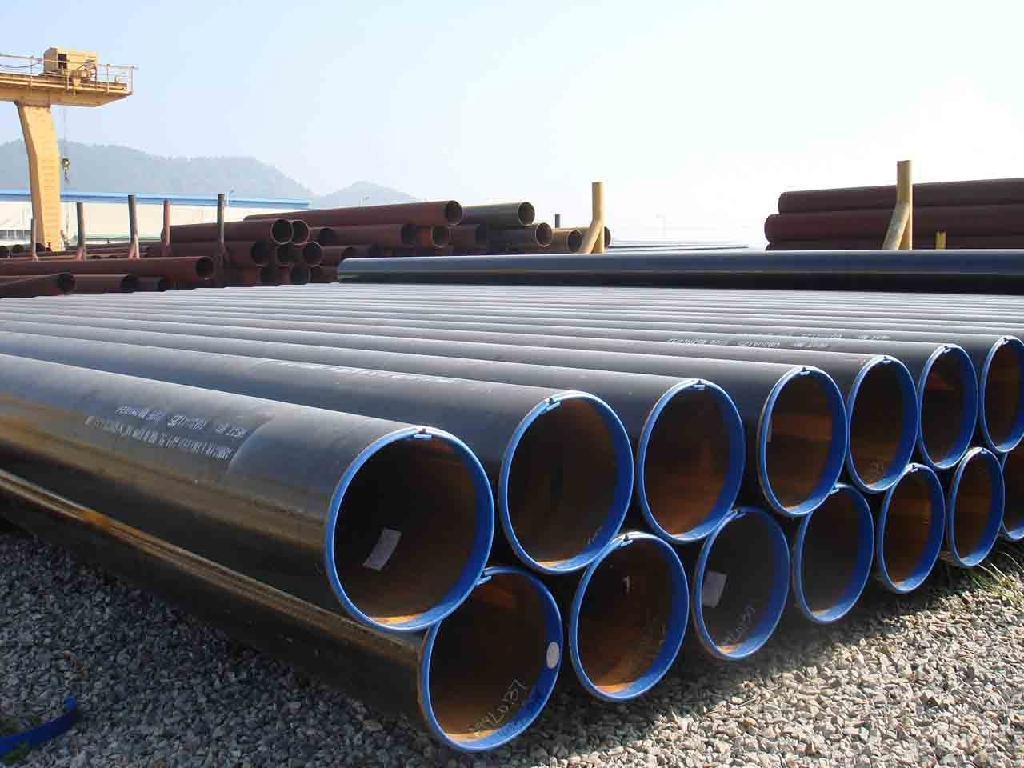 ️️
️️API 5L · ASTM A106 · A312 · A335 · A790 · A333View Pipes →
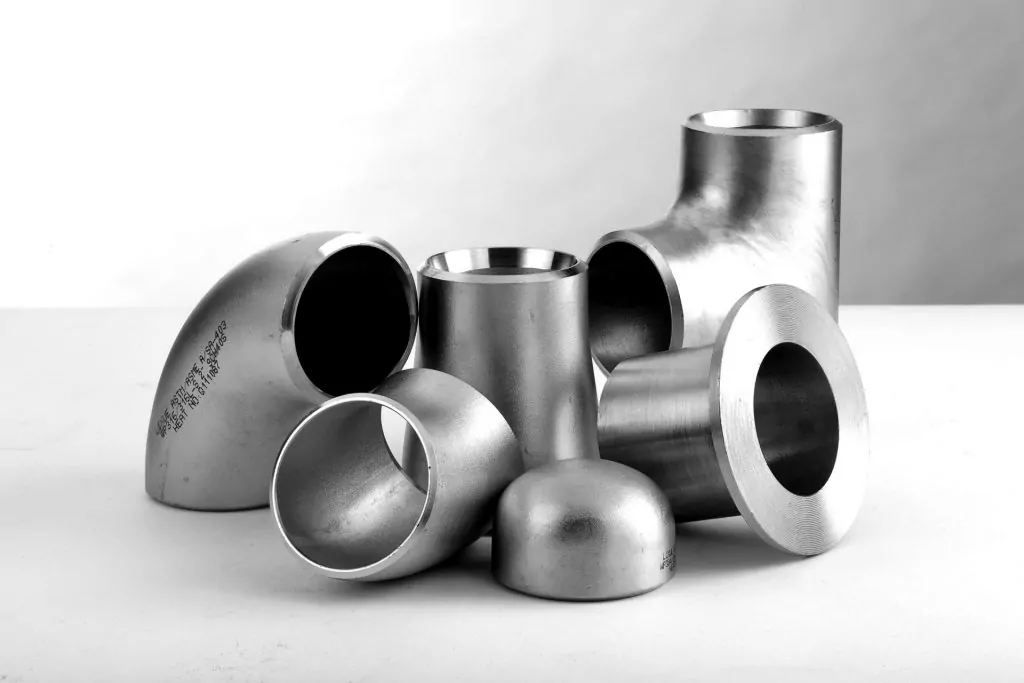
ASME B16.9 · B16.11 · MSS SP-75 · MSS SP-97View Fittings →
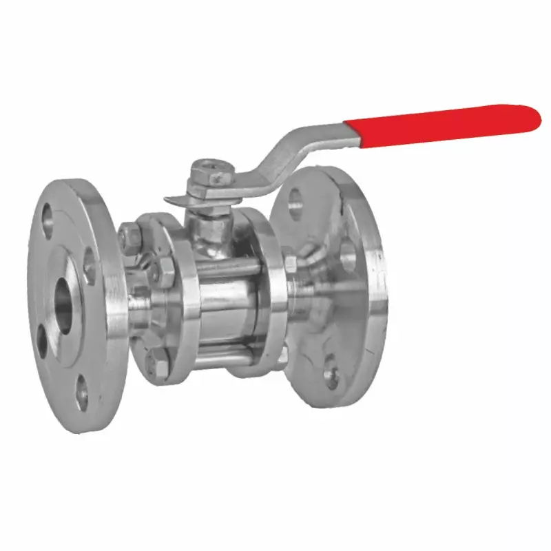
API 600 · API 6D · BS 1873 — Gate, Globe, Ball, CheckView Valves →
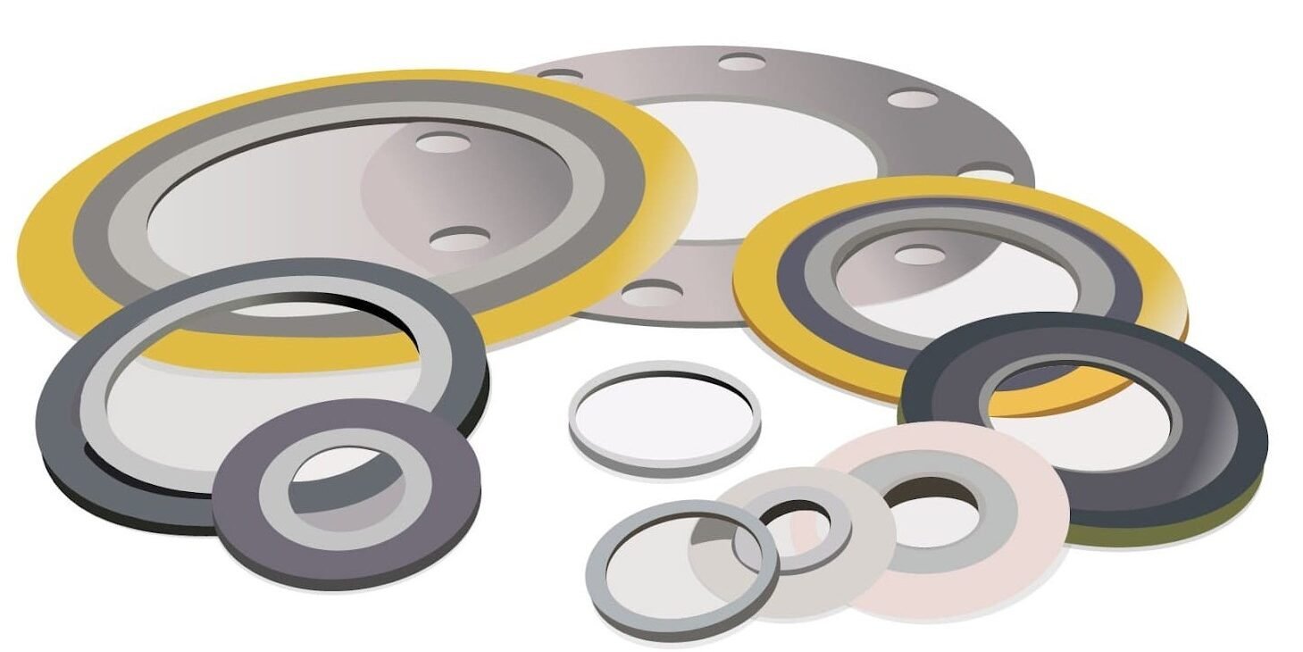
ASME B16.20 · B16.21 — SWG · RTJ · A193 B7View Gaskets →